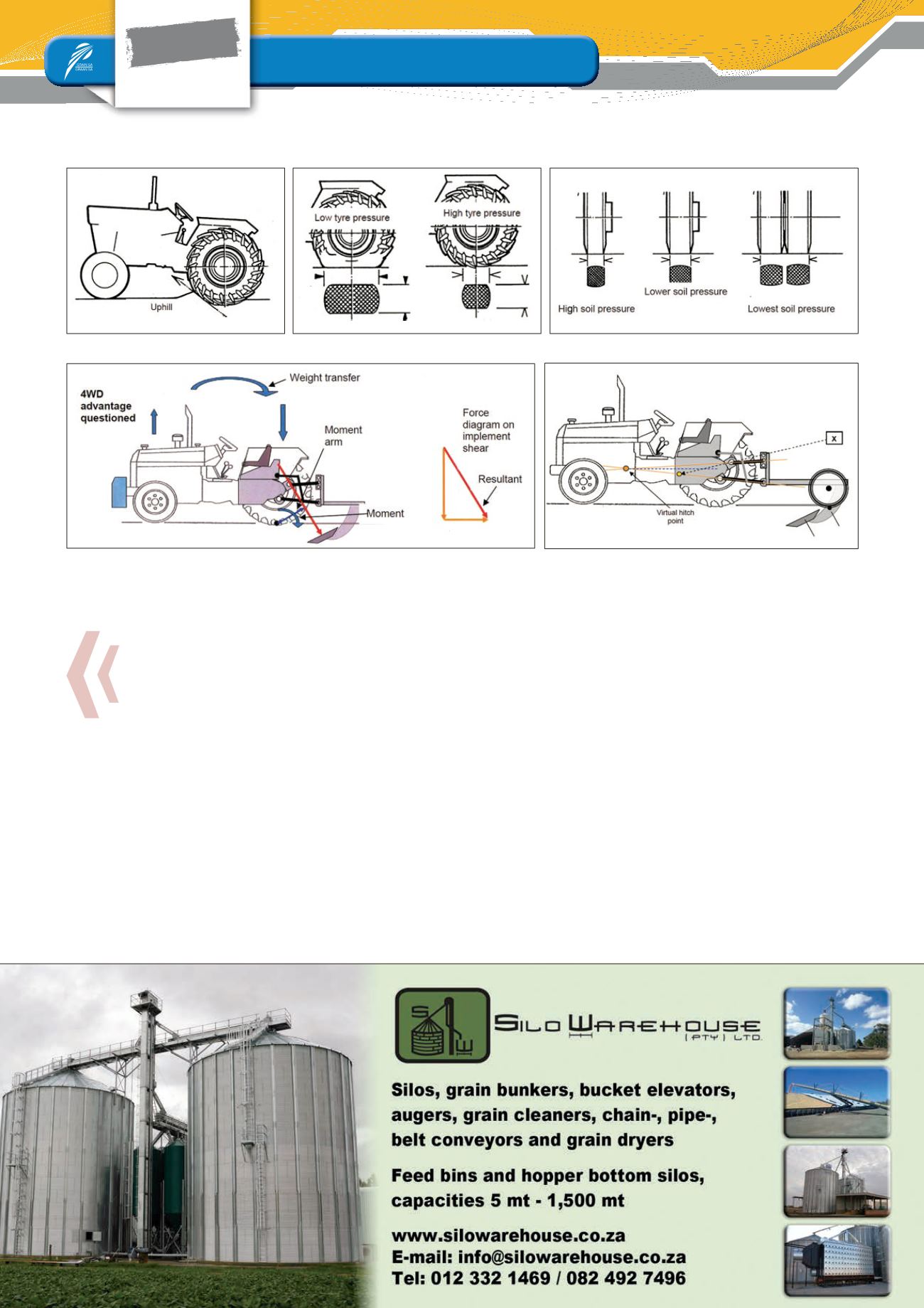

This can be a disadvantage for four-wheel drive tractors, because of
the traction losses at the front wheels of the tractor.
Implement hitching system: Three-point link-
age with depth control wheels
When using a depth control wheel on the implement, the force mo-
ment is between the centre of the ripper shears and the depth con-
trol wheel axle. This causes a downward pressure on both the rear
wheels and front wheels of the tractor. In this way, better traction will
be obtained over the front and rear wheels of the tractor, so a four-
wheel drive tractor will deliver good traction (
Figure 5
).
Different types of rippers
Rippers come in different shapes. The main differences are ripper
teeth shapes, some straight teeth designs and some with an arc
shape. Ripper teeth designs differ from each other because manu-
facturers try to create the best design for their product for best soil
penetration.
Then there are also the different ripper teeth shears that are being
used. The shears of course help to effectively loosen the soil. Manu-
facturers come with different ideas of shear designs to loosen the
soil. In most cases, the ripper shears are mounted at an angle to
achieve better penetration.
The other important component that is sometimes added is depth
control wheels, especially on the larger ripper frames. The function
of the depth control wheels is of course for more effective depth
control, but also to balance the weight and traction between the
tractor's front and rear wheels, which is ideal for four-wheel drive
tractors or tractors with belt tyres.
Ripping efficiency
Rip processing is not a cheap operation, so it's important to do
the operation as effectively as possible. The purpose of a ripping
operation is to loosen the soil or break a plough-pan layer. Effective
ripping can only be done when the maximum volume of soil is re-
leased. The energy input must therefore justify the output.
FOCUS
Implements and equipment
Special
A look at subsoiler or ripper efficiency
Figure 1: Rolling resistance.
Figure 4: Implement hitching.
Figure 5: Implement hitching with depth control wheel.
Figure 2: Tyre pressure.
Figure 3: Tyre width.


